The Modules Tool
- 13 Apr 2026
- 9 Minutes to read
- Contributors

- Print
- PDF
The Modules Tool
- Updated on 13 Apr 2026
- 9 Minutes to read
- Contributors
- Print
- PDF
Article summary
Did you find this summary helpful?
Thank you for your feedback
Applies to: Lasernet Core 11
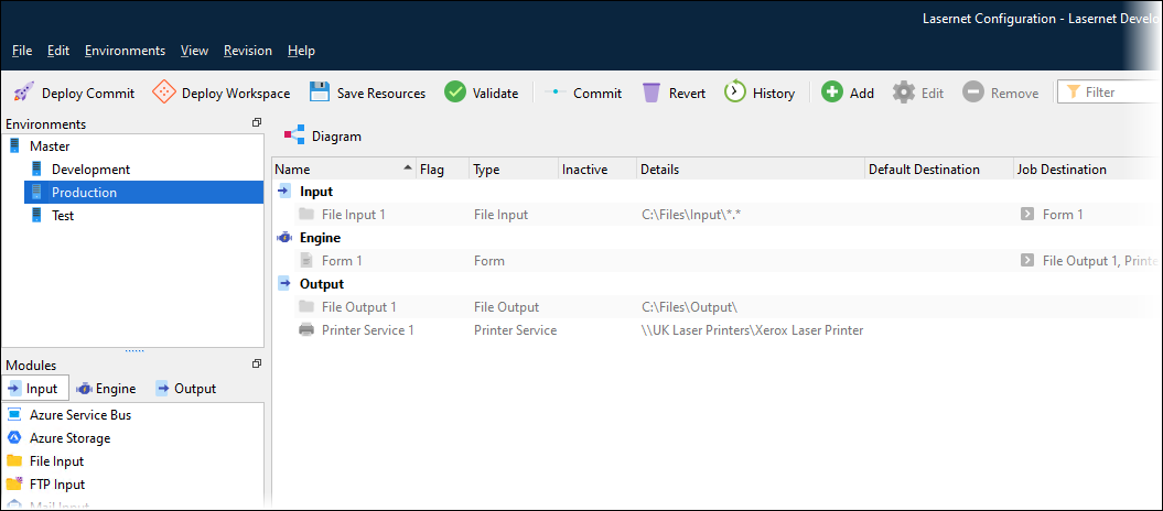
This is where all input modules, engines, and output modules are managed and designed into a workflow. To open the Modules tool, click Modules in the Tools pane.
The Environment pane at the upper-left shows which environment has been selected (as the environment that you are managing modules for).
.png)
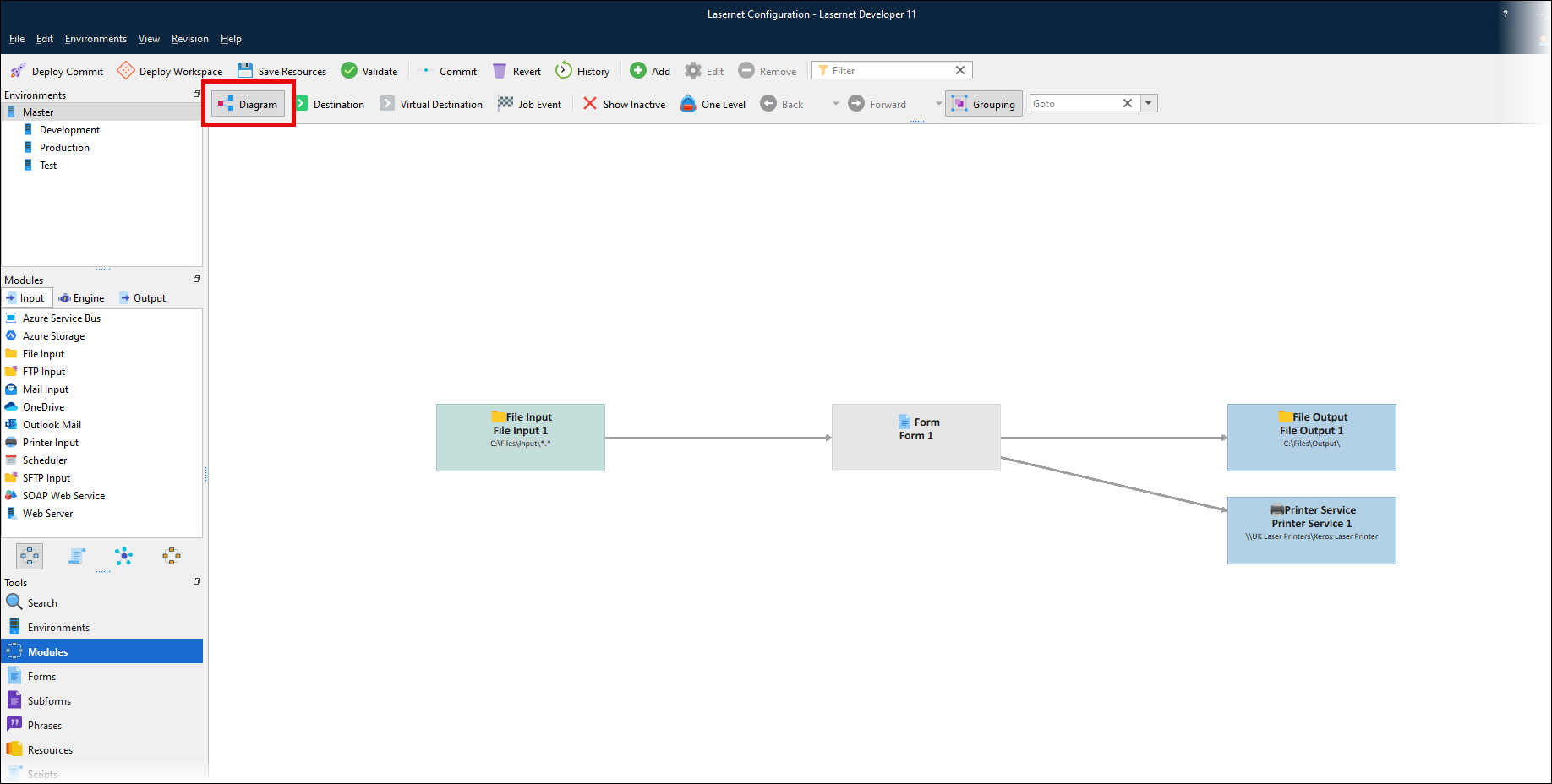
Diagram Mode and List Mode
You can view and maintain the modules in two modes. By clicking the Diagram button (in the toolbar above the main area), you can switch between diagram mode (default) and list mode. In both modes you can manage all modules and maintain their settings, either by double-clicking on the module or by setting the properties from the property editor (View > Properties).
.png)
Master Environment
The Master environment is the template environment. Any module added to the Master environment is inherited by all environments in the list. Any module added to a specific (non-Master) environment will run only in the environment that it is assigned to.
When changing to another environment, the modules added to Master are greyed out (see example below). Modules that are not grayed out will be available for the selected environment only and cannot be inherited by any other listed environment.
To move a module from its assigned environment to a different environment, select the module’s assigned environment, right-click the module, click Move to, then select the environment that you want to move the module to.
Inactive Modules
Modules can be marked as inactive. This means that they will not be started when uploading the configuration to a Lasernet Core environment. To toggle a module between active and inactive status, right-click the module and then select Toggle Inactive. If a module is inactive, it is marked by a red cross in the Inactive column.
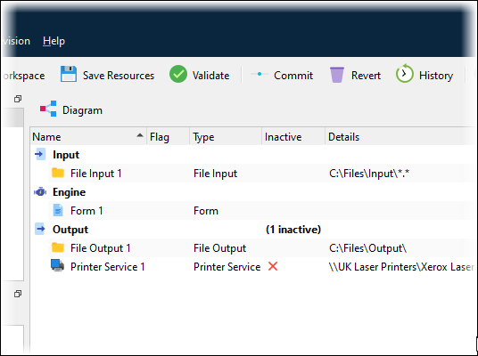
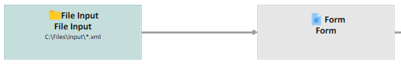
Diagram Mode
Diagram mode is an alternative to the list view. You can toggle between views using the Diagram button above the modules.
When diagram mode is toggled on, you are presented with a top-down overview of your configuration. This makes it much easier to see how jobs are passed between the modules in the configuration.
In Diagram mode you can create and design the configuration in the same way as in the list view.
Add a Module to the Configuration
New modules can be added by dragging them from the Modules pane on the left side of the screen onto the diagram, or by using the Add button in the toolbar, or through the right-click menu in the diagram area.
Modify a Module That Is Part of the Configuration
Modules can be edited by using the property editor, double-clicking the module, clicking Edit in the toolbar, or using the right-click menu in the diagram area.
Delete a Module from the Configuration
To delete an object, select it and then press the Delete key, click the Delete toolbar button, or select Delete from the right-click menu in the diagram area.
Destinations / Job Events
Create new module destinations or Job Events by dragging a line between two modules. To use this method, the Destination mode button in the toolbar must be selected. Properties for the destination / Job Event are shown in the property editor.
You can double-click destination arrows to add or change properties and criteria.
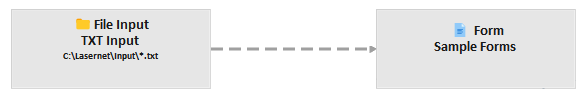
Lasernet Core represents destinations that have no criteria as a solid line.
Darker arrows indicate failover destinations. See Failover.
When criteria are added to a destination or Job Event, the arrow line is dashed.
Virtual Destination
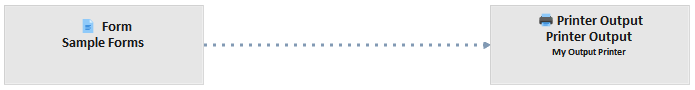
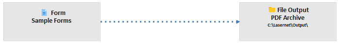
Destinations created via script commands and inserted on sheets in forms will not be visible as destination lines in the diagram view. To help create a more useful and accurate diagram showing which objects are actually linked together, you can drag virtual lines between modules. The virtual line has no function when a job is parsed, it is only used as a guide to help to visualize your configuration.
When virtual destinations are used, the arrow line is dotted.
One Level
The One Level Browsing feature enables you to view only modules ‘one level away’ from the selected module or destination/Job Event. To turn on this mode, ensure that Destination mode is turned off and then click One Level in the toolbar.
The selected module is indicated with a yellow background and blue border. The selected destination/Job Event is indicated in blue. One Level browsing makes it possible to navigate through a configuration, in the same way web pages are navigated in a browser. Back and forward is supported, both via the mouse buttons and the Back and Forward tool buttons.
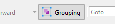
Grouping
Grouping mode uses a single diagram box to represent multiple modules that are of the same type and have exactly the same source or destination. Grouping modules can simplify the diagram view of the Lasernet Core configuration.
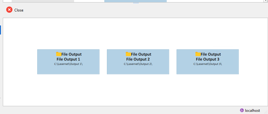
For example, if you have multiple File Output modules that are all linked to the same Form engine, Grouping mode will group these File Output modules into a single box.
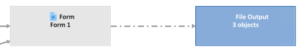
Lasernet Developer displays a dashed-dotted arrow between the group and the other involved module. This single arrow represents the multiple destination relationships between the modules in the group and the other involved module.
Click Group (above the diagram) to group modules.
To display all the objects in the group in a dedicated area of the diagram, double-click the group.
Module Selection
The Goto list in the toolbar above the diagram displays a list of modules in the configuration. To select a module, click it or type its name. The module is then highlighted and scrolled into view.
Change Indicators on Modules
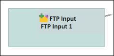
If you add a module to the workflow or modify a module (for example, by making it inactive), Lasernet Developer displays indicators on the module icons.
Added module (plus icon):
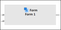
Modified module (square icon):
In the Commit window, deleted modules are denoted by a red minus icon.
Modifiers
Modifiers can be run on the enter or exit side of modules. Enter modifiers are listed above the box and exit modifiers are listed below.
The example below shows PDF encryption running as an exit modifier (below module):
Destinations
Input modules and engines have a Destinations tab in their Properties window.
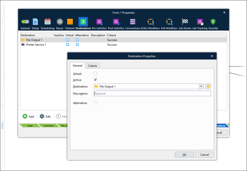
This tab enables you to specify one or more modules and engines as destinations for the job (if the input module or engine successfully processes the job). To control routing the job to particular destinations in specific scenarios, you can add criteria to destinations.
As mentioned in Destinations / Job Events, you can also add destinations by dragging between modules in the diagram.
To control job routing in scenarios where an engine or an output module fails during its Processing stage, use the Failover tab.
System Destinations
A list of predefined system destinations is available in Lasernet Developer. When listing available Destinations for a module, the system destinations will appear in the System section. The names of the system destinations are Default, Null, Preview, and Webservice. Lasernet Developer hides particular system destinations if the currently defined workflow doesn’t support them.
To force Lasernet Developer to list all available system destinations, click the All (sun) icon beside the Destination list.
.png)
Description of each system destination:
Default | In the Destination tab of an input module, you can define a Default destination:
When a job is being processed by the input module, the value defined as the default destination will be stored in the JobInfo named Default. If a module is configured to send a job to the Default destination, it will send it to the destination specified in that Default JobInfo. The Default destination enables this module to route jobs to different modules that follow it in the workflow, depending on which input module received the job. This dynamic control is possible because each input can specify a different Default destination. Default destination supports JobInfo substitution. |
Null | Sending a job to a null destination will stop the processing of a job in the workflow. Use the Null destination instead of assigning no destinations to a module, because if a module does not have any destinations, Lasernet Core will mark the job as failed. The Null destination is used if you want to ensure that a job is successfully stopped by the Job Engine. |
Preview | The Preview destination is added by default if a Web Server module is added to the configuration. For more info about the Preview destination, see Web Server Input. |
Webservice | The Webservice destination is added by default if a Web Server module is added to the configuration. If Webservice is selected as a destination, the job must be received by the Web Server module. When the job is received, an open TCP/IP connection is created by the Web Server and the Webservice module will redirect the job back to the client via the open connection. Afterwards, the connection will be closed. For more info about the Webservice destination, see Web Server Input. |

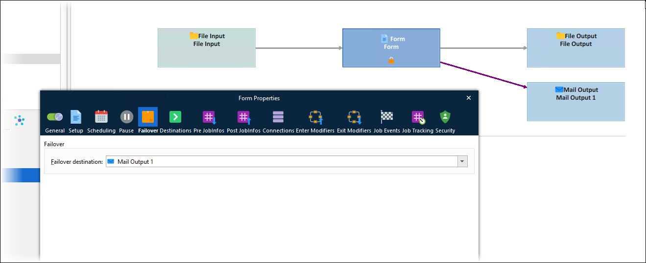
Failover
The Failover tab enables you to control job routing in the scenario where an engine or an output module fails during its Processing stage.
You can select one destination as the engine or output module’s failover destination.
The module diagram uses a darker arrow to indicate failover destinations.
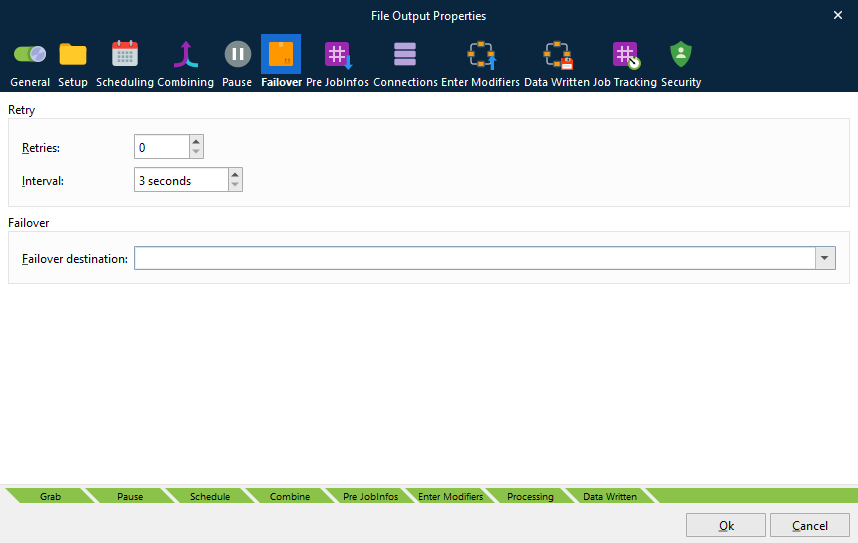
Retries
Output modules have a Retry area on their Failover tab. If an output module fails, Lasernet Core will try to run the module again at the time interval specified by Interval. Use Retries to control the number of times Lasernet Core will retry the module. If none of the retries succeed, Lasernet Core routes the job to the output module’s Failover destination.
Multithreaded Processing Options for Input Modules
The following input modules support multithreading processing:
Azure Service Bus
Azure Storage
File Input
FTP Input
Mail Input
OneDrive
Outlook Mail
SFTP Input
SOAP Web Service
The General tab of the Properties window of these input modules contains the following options:
Multi-thread: If this option is selected, the job generated when this input receives data can be processed by any available CPU core. The number of jobs (generated by this input) that Lasernet Core can simultaneously process is limited only by the number of CPU cores.
This option is enabled by default for the following modules:
Azure Service Bus Input
Azure Storage Input
File Input
Batch mode: If this option is selected, the jobs that this input creates will run in batch mode. Batch mode limits the proportion of CPU cores that are available to process jobs running in batch mode. This intentional limiting of CPU core usage ensures that sufficient cores remain available for other, higher-priority processing, while also enabling the multi-threaded, simultaneous processing of multiple batch mode jobs.
Configure inputs that are used to receive larger, lower-priority jobs to use batch mode.
Configure inputs that are used to receive higher-priority jobs (such as processing previews for users) to not use batch mode, so that they run in standard multi-threaded mode and utilize any available CPU cores.
If Multi-thread is not selected, Batch mode is grayed out.
In summary, when an input module receives a job:
If Multi-thread is not selected: A single CPU core is used to process jobs generated by this input.
If Multi-thread is selected and Batch mode is not selected: Each job generated by this input can be processed by any CPU core. The number of CPU cores available is not limited.
If Multi-thread and Batch mode are both selected: Each job generated by this input can be processed only by one of a limited number of CPU cores.